
Apoc Industries Ladder / Traction Bars Installation Guide
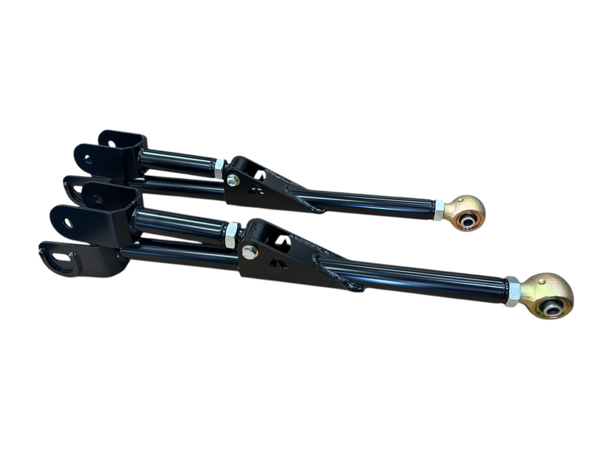
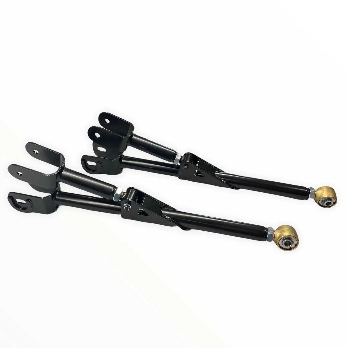
Apoc Industries Ladder / Traction Bars
Installation Guide | Apoc Industries | Bolt-On | Install Time: ~2.5 Hours | Drilling Required
Pre-Install Checklist
Required Tools
- Floor jack and jack stands
- Torque wrench
- Socket set — metric and standard, 3/8" and 1/2" drive
- Power drill
- CF frame mount style only: 1/2" drill bit
- BF frame mount style only: 1/2" drill bit and 11/16" drill bit, rivnut install tool (included), 13/16" wrench, 3/4" socket, impact wrench
- Marker or center punch
- Safety glasses, gloves, and steel-toed boots (PPE)
Identify Your Kit Configuration
Before starting, identify which axle mount style and frame mount style came with your kit:
-
Axle Mount Style:
- Axle Clamp — a clamp that wraps around the axle tube
- U-Bolt Mount — uses your existing factory U-bolts to attach to the axle
-
Frame Mount Style:
- CF (C-Channel / Open Frame) — bolts straight through the frame with standard 1/2" hardware
- BF (Boxed Frame) — uses rivnuts installed into drilled holes in a closed boxed frame
⚠ U-Bolt Mount fitment check: If your factory U-bolt nuts are on top of the leaf spring, the U-bolt mount style will not work for your vehicle. Do not proceed — contact Apoc Industries to discuss exchanging for the correct mount style for your application.
Parts Checklist
Verify all items against your packing slip before beginning installation.
- 2x Traction bars (driver and passenger side)
- 2x Axle mounts (clamp style or U-bolt style — per your kit)
- 2x Frame mounts (CF or BF style — per your kit)
- Complete Grade 8 hardware kit
- BF kits include: Rivnuts and rivnut install tool
Hardware Torque Reference
| Fastener | Location | Torque Spec |
|---|---|---|
| Rivnuts (BF frame mount) | Installed into boxed frame holes | 50 ft-lbs |
| 1/2" frame mount bolts (CF mount) | Frame mount to C-channel frame | 100 ft-lbs |
| Traction bar end bolts | Both axle and frame mount ends | 140 ft-lbs |
| Axle clamp bolts | Clamp around axle tube | 50 ft-lbs |
| U-bolt plate nuts | U-bolt axle mount | Refer to factory U-bolt torque spec for your vehicle |
Step-by-Step Installation Sequence
Step 1 — Install the Axle-Side Mount
Choose the instructions for your axle mount style:
🔧 Axle Clamp Style:
- Position the axle clamp around the axle tube just inboard of the leaf spring, toward the center of the axle
- The clamp should be positioned as directly below the frame rail as possible so the traction bar will run parallel and in line with the frame mount
- Tighten the clamp snugly — do not fully torque yet
🔧 U-Bolt Mount Style:
- Confirm your factory U-bolt nuts are located on the bottom of the axle — if they are on top of the leaf spring, do not proceed. Contact Apoc Industries to discuss exchanging for the correct mount style for your vehicle
- Remove the factory U-bolt nuts and washers from the bottom of the axle — leave the factory axle plate in place
- Slide the APOC U-bolt mount under the factory axle plate
- Reinstall in this order from the ground up: nut → washer → APOC U-bolt mount → factory axle plate → axle tube
- Reinstall the washers and nuts and tighten snugly — do not fully torque yet
Step 2 — Install Traction Bars into Axle Mounts (Both Sides)
- Insert each traction bar into its axle mount — either the adjustable end or the fixed end can go into the axle mount, it does not matter which way
- Leave all bolts hand-tight only — do not torque yet
- Thread the adjustable end out approximately 1" from its shortest position on each bar to leave room for adjustment later
Step 3 — Attach Frame Mounts to Traction Bars and Verify Clearance on Both Sides Before Drilling
⚠ Important: Before drilling any holes, check the frame mount location on both sides for clearance and symmetry. You do not need to check both sides at the same time — go one side at a time, but confirm both sides are clear and positioned correctly before drilling either one.
- Bolt the frame mount onto the opposite end of each traction bar — hand-tight only
- On one side, lift the frame mount up to the underside of the frame rail and check for clearance issues with fuel lines, brake lines, wiring, exhaust, and the fuel tank
- Once a good location is found, mark it with a marker or center punch — one hole on the side of the frame and one hole on the bottom of the frame
- Repeat on the opposite side, verifying clearance and marking the location before drilling
- Confirm both sides are marked symmetrically before proceeding to drill
Step 4 — Drill Initial Holes and Mount the Frame Brackets
CF Frame Mount Style (C-Channel / Open Frame — Bolt-Through):
- Use a 1/2" drill bit for all frame holes
- Drill through the marked locations with the frame mount held in position — the mount holes act as a guide
- Insert the supplied 1/2" bolts through the frame mount and frame — install nuts on the inside of the frame and tighten snugly
- Use the remaining holes in the frame mount as a guide to drill all remaining holes, then install all hardware hand-tight
BF Frame Mount Style (Boxed Frame — Rivnuts):
- With the frame mount held in position, drill the two marked holes using a 1/2" drill bit — use the frame mount holes as a guide for accurate placement
- Remove the frame mount, then re-drill all holes to 11/16" — this larger size allows the rivnut to slide into the hole
- Rivnut Installation: Use the included install tool, which consists of a 1/2" bolt, tall nut, and washers. Assemble in this order: rivnut → washer → tall nut → washer → bolt, snugged up so the rivnut is on the end of the bolt
- Insert the rivnut into the drilled hole
- Hold the tall nut with a 13/16" wrench — do not let it spin
- Using an impact and a 3/4" socket, tighten the 1/2" bolt while holding the 13/16" wrench stationary — the rivnut will compress and lock into the frame
- Continue tightening until the wrench no longer wants to turn, then snug a little more — this is done by feel, do not overtighten as this will damage the threads in the rivnut
- Reverse the impact while still holding the 13/16" wrench and back the bolt out — the rivnut must remain stationary and not spin. If it spins while backing out, it needs to be tightened more before the bolt is removed
- Repeat for all remaining holes on both sides
- Once all rivnuts are installed, reposition the frame mount and bolt it to the frame using the supplied 1/2" bolts threading into the rivnuts — use the frame mount holes to guide drilling any remaining holes before installing those rivnuts
Step 5 — Torque All Fasteners
With all mounts fully installed on both sides, torque all hardware using a calibrated torque wrench:
- Axle clamp bolts: 50 ft-lbs
- U-bolt plate nuts (U-bolt mount style): Refer to factory U-bolt torque spec for your specific vehicle
- Traction bar end bolts (both axle and frame mount ends): 140 ft-lbs
- CF frame mount 1/2" bolts: 100 ft-lbs
- BF frame mount bolts (into rivnuts): 50 ft-lbs
- Mark all torqued fasteners with a torque stripe for visual verification
Step 6 — Set Traction Bar Preload
With all mounts torqued, the final step is setting the correct preload on the traction bars. This must be done with the vehicle on the ground at ride height.
💡 No Preload (Recommended for Most Users):
- With the vehicle on the ground at ride height and no extra weight in the bed, remove one end of the traction bar from its mount — this allows the leaf spring to articulate freely
- Adjust the adjustable end so the bolt slides easily into the mount with no resistance — this is the neutral position
- In this setting the leaf springs have some travel before the traction bar engages, maintaining a comfortable ride for daily driving
- Reinstall the bolt and torque to 140 ft-lbs
- Repeat on the opposite side
💡 With Preload (For Constant Towing or Persistent Wheel Hop):
- Remove one end of the traction bar from its mount first — this allows the leaf spring to articulate freely when weight is added
- Place weight in the truck bed to simulate your typical payload and let the rear suspension compress naturally
- With the weight in the bed, adjust the traction bar length so the bolt slides easily into the mount with no resistance under load
- Reinstall the bolt and torque to 140 ft-lbs
- Repeat on the opposite side
- When the weight is removed, the traction bars will be preloaded against the leaf springs — this stiffens the rear suspension slightly but provides better control and reduced wheel hop under a payload
Post-Install Notes
- Re-check all fastener torque after 50–100 break-in miles
- Inspect all hardware for loosening at each oil change interval
- Note for 1994–2002 Dodge Ram with BDS long arm kits: The frame-side bracket may interfere with the long arm kit. The frame mount can be installed reversed for better clearance
- Note for 2003–2013 Dodge Ram 3500 with factory airbags: These bars are not a direct bolt-on for this application. Contact Apoc Industries for the weld-on tab option
- Note for 2011–2016 Ford Super Duty: Some models may require trimming or removal of the skid plate near the fuel tank for clearance
Safety Disclaimers
This installation guide is provided for reference purposes. Apoc Industries assumes no liability for improper installation, use of incorrect torque values, or failure to follow all safety procedures. Always have suspension work inspected by a qualified mechanic and comply with all local laws regarding vehicle modifications.
Apoc Industries | apocindustries.com | Document Version: v1.0

865-983-5004
Customer Service
Phone support available 9 AM–5 PM EST, Monday–Friday. Call us with questions or leave a message in the chat box—we'll respond during business hours.
Blog posts
Why 2014-2026 Ram 2500 Trucks Need Adjustable Radius Arms After a Lift
How adjustable radius arms help 2014–2026 Ram 2500 trucks control axle position, caster, and front-suspension articulation from stock height through a 10-inch lift.
Why 2005-2022 Ford Super Duty Trucks Need Adjustable Radius Arms After a Lift
A practical look at how lifting a 2005–2022 Ford Super Duty changes front-end geometry, and how adjustable radius arms and flex joints help restore control on the road and articulation off-road.

Tire & Wheel Fitment Guide: 2014-2026 Ram 2500/3500 with a Leveling Kit
Running a leveling kit on your 2014-2026 Ram 2500 or 3500? Here's exactly what tire and wheel specs you need for a clean, no-rub fit — including Ram-specific offset and track bar tips.