
2014-2026 ram 2500/3500 Adjustable 4-Link Install Instructions
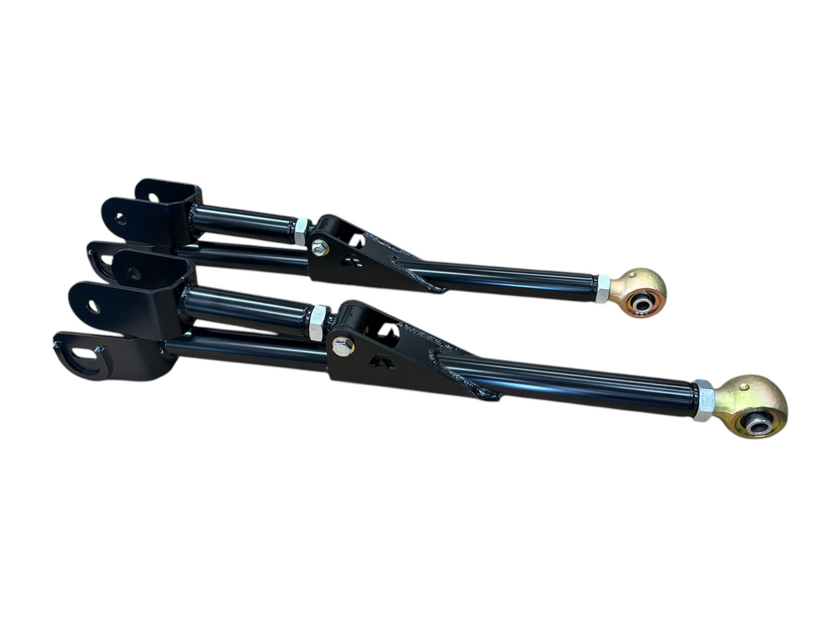
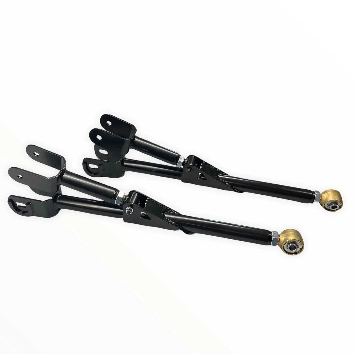
2014–2026 Ram 2500/3500 Adjustable 4-Link Conversion Kit
Installation Guide | Apoc Industries | Fits: 2014–2026 Ram 2500/3500 | 2–10" Lift
Overview
This guide covers the installation of the Apoc Industries adjustable 4-link conversion kit as an upgrade from the factory radius arm suspension system or an existing 4-link system. The goal of the 4-link conversion is to improve suspension geometry, gain caster adjustment capability, and allow precise axle centering in the fenderwell. This guide assumes the customer is upgrading the front suspension only and is not performing a complete lift installation at the same time.
Pre-Install Checklist
Required Tools
- Floor jack and jack stands
- Torque wrench
- Socket set — metric and standard, 3/8" and 1/2" drive
- Power drill with 1/2" drill bit
- Digital angle finder or caster gauge
- Grease gun
- Loctite (recommended for jam nuts)
- Safety glasses, gloves, and steel-toed boots (PPE)
Determine Your Lift Height Before Starting
- Measure your current lift height accurately before beginning — if you have a coil spring lift plus an additional spacer, add both measurements together to get your total lift height
- Use the arm length chart below to set both upper and lower arms to the correct length for your lift height before installation
- Correct arm length is critical for proper axle centering and caster angle
Bushing Grease — Important
⚠ All Apoc Industries polyurethane bushings must be lubricated with silicone grease only. Never use petroleum-based grease on polyurethane bushings — petroleum grease will break down the polyurethane material and cause premature bushing failure.
Safety Warnings
⚠ Always support the vehicle securely on jack stands before working under it. Never rely solely on a floor jack. Keep wheels on the vehicle during this installation to allow easier axle movement.
Arm Length Chart
Set arms to the following center-to-center lengths based on your total lift height. Measure total lift height by adding coil spring lift and any spacer together.
| Lift Height | Upper Arm Length | Lower Arm Length |
|---|---|---|
| 2" | 35 7/16" | 41 3/4" |
| 3" | 35 3/8" | 41 5/8" |
| 4" | 35 1/4" | 41 5/8" |
| 5" | 35 3/16" | 41 11/16" |
| 6" | 35 1/8" | 41 3/4" |
| 7" | 35 3/16" | 41 13/16" |
| 8" | 35 1/4" | 41 7/8" |
| 9" | 35 5/16" | 42" |
| 10" | 35 7/8" | 42 1/8" |
Hardware Torque Reference
| Fastener | Location | Torque Spec |
|---|---|---|
| Factory radius arm bolt (reused) | Upper arm — factory radius arm bolt hole | 222 ft-lbs |
| New supplied 3/4" bolt | Lower arm — new APOC bracket hole below factory bracket | 222 ft-lbs |
| New supplied 1/2" bolt | Rear hole drilled through frame to prevent bracket shift | 222 ft-lbs |
| Factory alignment cam bolts (reused) | Lower arm axle-side mount | 158 ft-lbs — torqued last after caster is set |
| Jam nuts | All adjustable arm ends | Tighten firmly — apply Loctite to prevent loosening |
Step-by-Step Installation Sequence
Step 1 — Support the Vehicle and Prepare the Axle
- Support the frame at ride height or just slightly higher using jack stands — the vehicle must be stable and level throughout the install
- Leave the wheels on the vehicle — this makes it easier to move the axle during installation
- Place a floor jack under the front differential/pinion with no upward pressure — just enough contact to prevent the axle from rolling forward when the radius arms are removed
Step 2 — Remove the Factory Radius Arms
- Remove one radius arm at a time — do not remove both before having the floor jack in place under the pinion
- Remove both radius arms completely and set the factory radius arm bolts aside — these will be reused
- Set the factory alignment cam bolts aside as well — these will also be reused on the lower arm axle-side mount
- With both arms removed the axle is now free to be positioned during installation
Step 3 — Install the 4-Link Frame Brackets (Both Sides)
⚠ Note: The APOC 4-link bracket nests inside the factory radius arm bracket. The factory bracket has only one bolt hole — this becomes the upper arm mount. A 1/2" hole must be drilled through the frame to prevent the bracket from shifting under hard braking.
- Slide the APOC 4-link bracket up inside the factory radius arm bracket so it is nested in place
- Insert the factory radius arm bolt back through the original hole to hold the APOC bracket in position — no nut needed at this stage, just insert the bolt to keep the bracket from moving
- With the bracket held in place, use the rear hole in the APOC bracket as a guide to mark the drilling location on the frame
- Remove the bracket, then drill a 1/2" hole through the frame at the marked location — this prevents the 4-link bracket from shifting rearward under hard braking
- Reinstall the APOC bracket inside the factory bracket, reinsert the factory radius arm bolt through the original hole to hold it in place, and install the supplied 1/2" bolt through the newly drilled frame hole — hand-tighten the 1/2" bolt only
- Repeat on the opposite side
Step 4 — Set Arm Lengths and Install Grease Fittings
- Set both upper and lower 4-link arms to the correct length from the arm length chart above
- Install all grease fittings into the arm ends now, before the arms are installed on the truck — this is much easier with the arms off the vehicle
- Lubricate all polyurethane bushings with silicone grease before installation — do not use petroleum-based grease
Step 5 — Install the Upper 4-Link Arms
- Install the upper arms first — you may need to use the floor jack to roll the axle forward slightly to allow the arms to fit into position
- The axle-side upper arm mount reuses the factory bolts — install and hand-tighten only
- The frame-side upper arm mount uses the factory radius arm bolt (reused) through the original factory hole — install with nut and hand-tighten
- Do not torque yet
Step 6 — Install the Lower 4-Link Arms
- Install the lower arms after the uppers are in place
- The axle-side lower arm mount uses the factory alignment cam bolts (reused from the original suspension) — reinstall these in the axle-side lower arm mount and hand-tighten only
- The frame-side lower arm mount uses the supplied 3/4" bolt through the APOC bracket hole that extends below the factory bracket — install and hand-tighten only
- Do not torque yet
Step 7 — Lower to Ride Height and Verify Axle Position
With all arms installed hand-tight, lower the vehicle to ride height with the full weight of the truck on the wheels before checking anything or torquing any fasteners.
- Check that the coil spring is not making contact with the sway bar end links — if it is, the axle is too far forward. This typically means the lift height measurement was off and the actual lift is less than expected. Recheck your total lift height (coil spring lift + any spacer) and adjust arm lengths accordingly
- Verify the axle appears centered in the fenderwell on both sides — the recommended arm lengths are designed to recenter the axle and eliminate tire rubbing
- Confirm the coil springs are sitting straight and not binding
Step 8 — Torque All Fasteners Except the Alignment Cam Bolts
With the vehicle at ride height and axle position confirmed, torque all hardware except the factory alignment cam bolts — those are done last after caster is set:
- Factory radius arm bolt (upper arm frame-side): 222 ft-lbs
- Supplied 3/4" bolt (lower arm frame-side): 222 ft-lbs
- Supplied 1/2" bolt (rear frame hole): 222 ft-lbs
- Jam nuts (all adjustable arm ends): Tighten firmly — apply Loctite to prevent loosening under vibration
- Mark all torqued fasteners with a torque stripe for visual verification
Step 9 — Set and Verify Caster, Then Torque the Factory Alignment Cam Bolts
Caster is the final adjustment. With the vehicle at ride height and all other fasteners torqued:
💡 What is Caster? Caster is the angle of the steering axis — specifically, how far the upper ball joint is behind the lower ball joint when viewed from the side. If you drew a line through the center of the upper and lower ball joints, that line should be tilted rearward 3.5–5 degrees from vertical. Caster is what keeps your truck tracking straight on the road and causes the steering wheel to return to center after a turn. If your truck wanders on the highway or pulls every time it hits a dip in the road, you likely need more caster.
How to Measure Caster:
- Place a digital angle finder on the machined flat surface on top of the steering knuckle, around the upper ball joint — this surface is designed for this measurement
- The reading should be between 3.5 and 5 degrees
- Apoc Industries recommends no less than 3.5 degrees — factory Ram spec is approximately 3.5 degrees
- For trucks running offset wheels, Apoc recommends approximately 5 degrees for best on-road tracking and steering return
Adjusting Caster:
- Use the factory alignment cam bolts on the lower arm axle-side mount for fine caster adjustment
- If more adjustment range is needed than the cam bolts provide, adjust the lower arm length in or out to reach the desired caster angle, then use the cam bolts for final fine-tuning
- Once caster is set to your preference, torque the factory alignment cam bolts to 158 ft-lbs
Post-Install Notes
- A professional front-end alignment is strongly recommended after installation to verify caster, camber, and toe settings
- Re-check all fastener torque after 50–100 break-in miles
- Grease all arm end fittings at each oil change interval using a grease gun
- Inspect all hardware for loosening at each oil change interval
- Always use silicone grease on polyurethane bushings — petroleum-based grease will break down the polyurethane and cause premature failure
Safety Disclaimers
This installation guide is provided for reference purposes. Apoc Industries assumes no liability for improper installation, use of incorrect torque values, or failure to follow all safety procedures. Suspension modifications significantly affect vehicle handling characteristics. Always have suspension work inspected by a qualified mechanic and comply with all local laws regarding vehicle modifications and lift height limits.
Apoc Industries | apocindustries.com | Document Version: v1.0

865-983-5004
Customer Service
Phone support available 9 AM–5 PM EST, Monday–Friday. Call us with questions or leave a message in the chat box—we'll respond during business hours.
Blog posts
Why 2014-2026 Ram 2500 Trucks Need Adjustable Radius Arms After a Lift
How adjustable radius arms help 2014–2026 Ram 2500 trucks control axle position, caster, and front-suspension articulation from stock height through a 10-inch lift.
Why 2005-2022 Ford Super Duty Trucks Need Adjustable Radius Arms After a Lift
A practical look at how lifting a 2005–2022 Ford Super Duty changes front-end geometry, and how adjustable radius arms and flex joints help restore control on the road and articulation off-road.

Tire & Wheel Fitment Guide: 2014-2026 Ram 2500/3500 with a Leveling Kit
Running a leveling kit on your 2014-2026 Ram 2500 or 3500? Here's exactly what tire and wheel specs you need for a clean, no-rub fit — including Ram-specific offset and track bar tips.